ISO 15171 standard specific the connections for fluid power and general use in Hydraulic couplings for diagnostic purposes, it is hydraulic test Coupling not for connection under pressure.
Scope of hydraulic test fittings:
This part of ISO 15171 specifies dimensions, performance requirements and test procedures for the male quick action half of a metric coupling with an M14 x 1,5 straight stud end to mate with an ISO 6149-1 port, to be used for diagnostic purposes. Couplings in accordance with this part of ISO 15171 are not designed to connect under pressure. The coupling is designed for use in hydraulic systems that use mineral oil.
Working pressure of test port fittings
Couplings in accordance with this part of ISO 15171 may be used at a maximum working pressure of 40 MPa [400 bar)]. The permissible working pressure depends upon the materials, design, working conditions, application, etc.
Test of hydraulic test fittings
Conformance to the dimensional information in this part of ISO 15171 does not guarantee rated performance. Each manufacturer should perform testing in accordance with the specification contained in this part of ISO 15171 to assure that components comply with the performance rating.
Burst and cyclic endurance (impulse) pressures
The male half of the coupling shall meet at least a burst pressure of 160 MPa (1 600 bar) and a cyclic endurance(impulse) pressure of 53,2 MPa (532 bar) when tested in accordance with 4.4.
Test methods
Testing shall be conducted in accordance with ISO 8434-5 for burst, cyclic endurance (impulse) and vacuum. The test samples shall be tightened to the torque requirement given in ISO 6149-2 for the M14x 1,5 size stud end. After the cyclic endurance test, it shall be possible to connect and disconnect the coupling with the female half without leakage, binding or malfunction. Test results shall be reported using the form given in ISO 8434-5.
Design
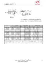
Design and dimensions shall conform to those given in Figure 1. Stud end and 0O-ring shall be in accordance with ISO 6149-2.
Unless otherwise agreed upon between the supplier and purchaser, seals for stud ends shall be included in the delivery.
a Width across flats
b Maximum engagement
C Hardness 42 HRC to 55 HRC in contact area
D Ra≤2,5 um for 4,57 mm length
E Valve open
F This groove is for product marking and attachment of protective cap. Alternate marking location is on hex flats.
9 O-ring .
H Stud end in accordance with ISO 6149-2
Identification groove in accordance with ISO 6149-2
Figure 1一Dimensions and tolerances of male half of diagnostic coupling