ISO 6164:2018 square flange Assembly procedures and screw torque levels for flange connections conforming to this document.

A.1 Ensure that the flange connection selected meets the requirements of the application, e.g. rated pressure.
A.2 Ensure that the flange components and ports conform to this document and that the correct screw sizes and lengths are used.
A.3 Ensure that all sealing and surface interfaces are free of burrs, nicks, scratches and any foreign material.
A.4 To help minimize O-ring fall out, lubricate the O-ring with a light coat of the hydraulic fluid used in the system or a compatible oil, when necessary. Take special care, as excess lubricant may seep out of the joint and lead to a false indication of leakage.
A.5 Position the flanged head and the flange clamps. Lubricate the screws on the thread portion and under the head portion. Use MoS 2 type lubricant. The use of paste lubricant with solid antifriction particles such as MoS 2 is recommended.
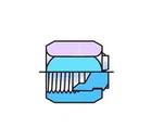
A.6 Hand tighten the screws in the sequence shown in Figure A.1, to ensure uniform contact at all four screw locations to prevent the flange from tipping, which can lead to the flange breaking during application of final torque.