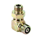
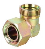
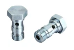
O-ring face seal connections tube fittings are according to SAE J1453 and ISO 8434-3 standards, Surface finish acceptance criteria for O-ring face seal groove design connection (typical for all styles) very important.
O ring groove dimensions drawing

a Pitch diameter.
b Groove outside diameter.
c Sharp edge or burr not allowed; break corner 0,15 max.
d Optional construction for shapes and long straights.
e Minimum full thread depth.
f Groove style A – Groove providing improved retention of O-ring – Option 1.
g Groove style A – Groove providing improved retention of O-ring – Option 2.
h Groove style B.
i Screw threads
SAE J1453 ORFS Groove and orfs o ring sizes chart as follows:

Dimensions in millimetres
O-ring Surface B d f i 1 i 5 d 4 Tube outside diameter Thread a Outside diameter Inside diameter nom. tol. ± 0,4 min. nom. tol. min. max.
6 9/16-18 UNF 2,4 ± 0,3 10 9 7,65 ± 0,16 11,08 6,1
8 5/8-18 UNF 2,4 ± 0,3 10 9 8,5 ± 0,16 11,93 6,95
10 11/16-16 UN 2,8 ± 0,4 11 10,5 9,25 ± 0,17 12,68 7,7
12 13/16-16 UN 2,8 ± 0,4 13 12 12,42 ± 0,19 15,85 10,87
16 1-14 UNS 3,1 ± 0,4 15,5 14 15,6 ± 0,2 19,08 14,1
20 1 3/16 -12 UN 3,7 ± 0,5 17 15 18,77 ± 0,22 22,27 17,25
22 1 5/16 -12 UN 3,7 ± 0,5 17,5 15,5 21,95 ± 0,23 25,45 20,43
25 1 7/16 -12 UN 3,7 ± 0,5 17,5 15,5 23,52 ± 0,24 26,97 21,95
30 1 11/1 6 -12 UN 3,7 ± 0,5 17,5 15,5 29,87 ± 0,29 33,38 28,3
38 2-12 UN 3,7 ± 0,5 17,5 15,5 37,82 ± 0,36 41,3 36,22
Dash Size O-Ring Cross-Section O-Ring Diameter
-005 0.070 0.101
-006 0.070 0.114
-007 0.070 0.145
a In accordance with ISO 68-2 and ISO 5864:1993, Class 2A, and Annex A, except for 1-14 UNS. See Annex A for 1-14 UNS thread dimensions.


